8,843 total views, 3 views today
In the previous tutorial (GPU Particle Force Field), we made a custom shader that could take in a position and radius representing a spherical displacement affector, or “force field”, to move the vertices of a particles and colour it based on its normalized offset.
In this tutorial, we’re going to work on a version of that same shader that can support multiple force fields using an array. The preview you see below was made simply by using the effect we build in this tutorial with the addition of the uniform particle grid from this previous tutorial.
[IMAGE REMOVED]
Grab the finished shader from the previous tutorial if you don’t already have it and let’s get started!
Part 1 – Vertex Shader
Create a copy of the previous shader file and change the name.
![]()
All I’ve done below in the source is add an ‘s’ to make “Field” plural… that’s all.
Shader "Custom/Particles/GPU Force Fields Unlit (Tutorial)"
Next, remove the two radius and position material properties. Where we’re going, we won’t need them anymore (because we’ll be assigning these directly to the shader force field array from a C# script).
Properties
{
_MainTex("Texture", 2D) = "white" {}

_ForceFieldRadius("Force Field Radius", Float) = 4.0
_ForceFieldPosition("Force Field Position", Vector) = (0.0, 0.0, 0.0, 0.0)

[HDR] _ColourA("Color A", Color) = (0.0, 0.0, 0.0, 0.0)
[HDR] _ColourB("Color B", Color) = (1.0, 1.0, 1.0, 1.0)
}
We’ll also remove the radius and position variables (lines 4 and 5) so we can replace them with the number of force fields (line 7) and a “tightly packed” force field array (line 8). We’ll store the position of each force field in XYZ, and its radius in W. We’ll use the count to terminate the loop we’ll use to iterate through each force field early so we don’t have to go through the entire array.
NOTE: I used an array size of 8, but you can use a much larger number like 64 if you want.
sampler2D _MainTex;
float4 _MainTex_ST;

float _ForceFieldRadius;
float3 _ForceFieldPosition;

int _ForceFieldCount;
float4 _ForceFields[8];

float4 _ColourA;
float4 _ColourB;
As an example with the array, the first force field would be defined as the position _ForceField[0].xyz and radius _ForceField[0].w.
Now we can work on changing up the function that calculates and returns the particle offset. The very first thing we’ll do is add a second parameter, “forceField”. Since we don’t have globals representing a single force field radius and position, we’ll pass in this information per-sphere as we loop through the array calling this function.
float4 GetParticleOffset(float3 particleCenter, float4 forceField)
Create two new variables at the top of the function to extract the radius and position.
float forceFieldRadius = forceField.w;
float3 forceFieldPosition = forceField.xyz;
That’s really all we needed to do, so we can now replace the _ForceFieldRadius and _ForceFieldPosition in the function with the two new variables that we just created as replacements. I’ve also change the 0.0 to a small value for the max function in line 12 to prevent the vertices from disappearing with multiple force fields.
Everything else is the same for now, and the function thus far is below.
float4 GetParticleOffset(float3 particleCenter, float4 forceField)
{
float forceFieldRadius = forceField.w;
float3 forceFieldPosition = forceField.xyz;

float distanceToParticle = distance(particleCenter, forceFieldPosition);
float forceFieldRadiusAbs = abs(forceFieldRadius);

float3 directionToParticle = normalize(particleCenter - forceFieldPosition);

float distanceToForceFieldRadius = forceFieldRadiusAbs - distanceToParticle;
distanceToForceFieldRadius = max(distanceToForceFieldRadius, 0.0001);

distanceToForceFieldRadius *= sign(forceFieldRadius);

float4 particleOffset;

particleOffset.xyz = directionToParticle * distanceToForceFieldRadius;
particleOffset.w = distanceToForceFieldRadius / (forceFieldRadius + 0.0001); // Add small value to prevent divide by zero and undefined colour/behaviour at r = 0.0.

return particleOffset;
}
With the modified offset function and array implemented, all we need to do to finish basic support for multiple force fields is update the actual vertex shader with the loop (the updated lines are 7 – 12).
NOTE: It may be faster to go over the entire array length rather than attempting to terminate early with a variable force field count. This is because the compiler will first attempt to unroll the loop by default. In that case, you’d have to create a new array every frame in the corresponding C# script that’s limited to the size of the number of force fields so that inactive fields are ignored OR set their radii to 0 so they don’t influence any particles (a better solution to prevent constant allocations).
v2f vert(appdata v)
{
v2f o;

float3 particleCenter = float3(v.tc0.zw, v.tc1.x);

float3 vertexOffset = 0.0;

for (int i = 0; i < _ForceFieldCount; i++)
{
vertexOffset += GetParticleOffset(particleCenter, _ForceFields[i]).xyz;
}

v.vertex.xyz += vertexOffset;
o.vertex = UnityObjectToClipPos(v.vertex);

// Initialize outgoing colour with the data recieved from the particle system stored in the colour vertex input.

o.color = v.color;

o.tc0.xy = TRANSFORM_TEX(v.tc0, _MainTex);

// Initialize outgoing tex coord variables.

o.tc0.zw = v.tc0.zw;
o.tc1 = v.tc1;

UNITY_TRANSFER_FOG(o,o.vertex);
return o;
}
We’ll come back to make some more changes to the vertex shader later, but for now let’s move on to the fragment shader.
Part 2 – Fragment Shader
The updated lines are from 12 – 19. Since multiple force fields are contributing to the offset of particles, we take the largest normalized offset from the entire loop and use that.
fixed4 frag(v2f i) : SV_Target
{
// sample the texture
fixed4 col = tex2D(_MainTex, i.tc0);

// Multiply texture colour with the particle system's vertex colour input.

col *= i.color;

float3 particleCenter = float3(i.tc0.zw, i.tc1.x);

float maxNormalizedOffset = 0.0;

for (int i = 0; i < _ForceFieldCount; i++)
{
maxNormalizedOffset = max(maxNormalizedOffset, GetParticleOffset(particleCenter, _ForceFields[i]).w);
}

col = lerp(col * _ColourA, col * _ColourB, maxNormalizedOffset);

col *= col.a;

// apply fog
UNITY_APPLY_FOG(i.fogCoord, col);
return col;
}
That was easy, wasn’t it? Unfortunately, without a C# script populating the force fields array, we can’t actually see anything happen (unlike with our previous shader with a single force field). On to the next part!
Part 3 – GPU Force Fields GameObject
The way I have my system setup is that any child transform of the game object with this component attached is considered a force field object. You can then dynamically add/remove transforms from the parent to create and destroy force fields.
I’ll go over the differences between this script and the single force field script from the previous tutorial.
First off, I have a constant internal variable specifying the maximum number of supported force fields that should match the array length in the shader (line 9).
I have an array of Vector4 forceFields at line 11 which I’ll then initialize to the max length at start and assign to the equivalent variables in the shader (lines 17 and 18). Unity is a bit strange in that the actual shader array isn’t initialized to its length until its set from an external script, which is why I do this immediately.
Every frame I update the count in the shader based on the number of children (line 23) and then loop through them to extract their position and radius which are assigned to the currently iterated force field vector inside the array (lines 25 – 33). Once the update loop is finished, I simply mirror this data to the shader array (line 35).
Finally, I’m just looping through the array within OnDrawGizmos so I can visualize the force field spheres (lines 40 – 46).
Below is the full C# script.
using System.Collections;
using System.Collections.Generic;
using UnityEngine;

[ExecuteInEditMode]
public class GPUParticleForceFields : MonoBehaviour
{
public Material material;
const int MAX_FORCE_FIELDS = 8; // Make sure this matches the shader global array size.

Vector4[] forceFields;

void Start()
{
// Needs to be set to the max supported array length as that determines the actual size on the shader.

forceFields = new Vector4[MAX_FORCE_FIELDS];
material.SetVectorArray("_ForceFields", forceFields);
}

void LateUpdate()
{
material.SetInt("_ForceFieldCount", transform.childCount);

for (int i = 0; i < transform.childCount; i++)
{
Transform childTransform = transform.GetChild(i);

forceFields[i] = new Vector4(

childTransform.position.x, childTransform.position.y, childTransform.position.z,
childTransform.lossyScale.x / 2.0f);
}

material.SetVectorArray("_ForceFields", forceFields);
}

void OnDrawGizmos()
{
for (int i = 0; i < transform.childCount; i++)
{
Transform childTransform = transform.GetChild(i);

float radius = childTransform.lossyScale.x / 2.0f;
Gizmos.DrawWireSphere(childTransform.position, radius);
}
}
}
Now you can do some really weird stuff.
[IMAGE REMOVED]
Part 4 – Uniform Radius
We’re going to add one final optional feature to the shader to help alleviate the “problem” with additive offset blending so that force fields blend together a little better. This’ll come at the cost of having variable radii (that is, a single uniform radius to be shared by all force fields in a material), but it may be more suitable in certain situations.
We’ll control whether we want the shader to use this feature using a static switch/toggle, so we need to add that in the material’s properties along with the uniform radius (lines 5 and 6). Note that I’m using a range slider because it’s easier to use in the editor (and more fun?), but you can use a regular value property or a larger slider range.
Properties
{
_MainTex("Texture", 2D) = "white" {}

[Toggle(_USEUNIFORMRADIUS_ON)] _UseUniformRadius("Use Uniform Radius", Float) = 0.0
_UniformRadius("Uniform Radius", Range(-10.0, 10.0)) = 1.0

[HDR] _ColourA("Color A", Color) = (0.0, 0.0, 0.0, 0.0)
[HDR] _ColourB("Color B", Color) = (1.0, 1.0, 1.0, 1.0)
}
We need to define a keyword for the switch as well (line 7).
CGPROGRAM
#pragma vertex vert
#pragma fragment frag
// make fog work
#pragma multi_compile_fog

#pragma shader_feature _USEUNIFORMRADIUS_ON

#include "UnityCG.cginc"
And of course, the uniform radius variable (line 7).
sampler2D _MainTex;
float4 _MainTex_ST;

int _ForceFieldCount;
float4 _ForceFields[8];

float _UniformRadius;

float4 _ColourA;
float4 _ColourB;
The way we’ll handle blending is by applying the uniform radius (lines 3 and 6 – 10) and then using the lowest offset value from all force fields. To get the lowest offset distance from function, we use the inout keyword with a parameter (line 1) so that we can pass in a value and also modify the original (essentially passing by reference to the original variable). This is used to update the input variable by comparing it against the current distance so that it’s always the smallest (line 27).
float4 GetParticleOffset(float3 particleCenter, float4 forceField, inout float minDistanceToParticle)
{
float forceFieldRadius;
float3 forceFieldPosition = forceField.xyz;

#ifdef _USEUNIFORMRADIUS_ON
forceFieldRadius = _UniformRadius + 0.0001;
#else
forceFieldRadius = forceField.w;
#endif

float distanceToParticle = distance(particleCenter, forceFieldPosition);
float forceFieldRadiusAbs = abs(forceFieldRadius);

float3 directionToParticle = normalize(particleCenter - forceFieldPosition);

float distanceToForceFieldRadius = forceFieldRadiusAbs - distanceToParticle;
distanceToForceFieldRadius = max(distanceToForceFieldRadius, 0.0001);

distanceToForceFieldRadius *= sign(forceFieldRadius);

float4 particleOffset;

particleOffset.xyz = directionToParticle * distanceToForceFieldRadius;
particleOffset.w = distanceToForceFieldRadius / (forceFieldRadius + 0.0001); // Add small value to prevent divide by zero and undefined colour/behaviour at r = 0.0.

minDistanceToParticle = min(minDistanceToParticle, distanceToParticle);

return particleOffset;
}
We can then modify the vertex shader part to keep track of and use the min distance if the uniform radius switch is active. The highlighted lines below indicate the changes to the shader.
I initialize the min distance variable to some large value so that subsequent iterations are gaurenteed to retrieve smaller values. If there was a “MAX_FLOAT” definition for HLSL, I’d use that… but there isn’t. So 99999.0 (or larger) will have to do (line 5).
v2f o;

float3 particleCenter = float3(v.tc0.zw, v.tc1.x);

float minDistanceToParticle = 99999.0;

float3 vertexOffset = 0.0;

for (int i = 0; i < _ForceFieldCount; i++)
{
vertexOffset += GetParticleOffset(particleCenter, _ForceFields[i], minDistanceToParticle).xyz;
}

#ifdef _USEUNIFORMRADIUS_ON

float3 normalizedVertexOffset = normalize(vertexOffset);

float uniformRadiusAbs = abs(_UniformRadius);
float minDistanceToUniformRadius = max(uniformRadiusAbs - minDistanceToParticle, 0.0);

uniformRadiusAbs *= sign(_UniformRadius);

vertexOffset = normalizedVertexOffset * minDistanceToUniformRadius;

#endif

v.vertex.xyz += vertexOffset;
o.vertex = UnityObjectToClipPos(v.vertex);
We also need to make a similar update to the fragment part (lines 5 and 10).
col *= i.color;

float3 particleCenter = float3(i.tc0.zw, i.tc1.x);

float minDistanceToParticle = 99999.0;
float maxNormalizedOffset = 0.0;

for (int i = 0; i < _ForceFieldCount; i++)
{
maxNormalizedOffset = max(maxNormalizedOffset, GetParticleOffset(particleCenter, _ForceFields[i], minDistanceToParticle).w);
}

col = lerp(col * _ColourA, col * _ColourB, maxNormalizedOffset);

col *= col.a;
The shader itself is now functional, and you should see the switch available as a toggle in the editor.
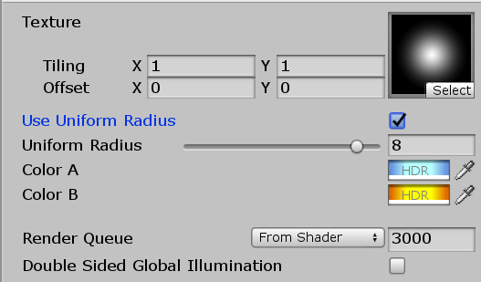
Here’s a comparison with the uniform switched turned off and on.
[IMAGE REMOVED]
All that’s left is to update our C# component so we can properly account for- and draw the uniform spheres (lines 3, 4, and 10).
void OnDrawGizmos()
{
bool useUniformRadius = material.GetFloat("_UseUniformRadius") == 1.0f ? true : false;
float uniformRadius = material.GetFloat("_UniformRadius");

for (int i = 0; i < transform.childCount; i++)
{
Transform childTransform = transform.GetChild(i);

float radius = useUniformRadius ? uniformRadius : (childTransform.lossyScale.x / 2.0f);
Gizmos.DrawWireSphere(childTransform.position, radius);
}
}
And look at that, we’re done!
Here’s the final shader code.
Shader "Custom/Particles/GPU Force Fields Unlit (Tutorial)"
{
Properties
{
_MainTex("Texture", 2D) = "white" {}

[Toggle(_USEUNIFORMRADIUS_ON)] _UseUniformRadius("Use Uniform Radius", Float) = 0.0
_UniformRadius("Uniform Radius", Range(-10.0, 10.0)) = 1.0

[HDR] _ColourA("Color A", Color) = (0.0, 0.0, 0.0, 0.0)
[HDR] _ColourB("Color B", Color) = (1.0, 1.0, 1.0, 1.0)
}

SubShader
{
Tags { "Queue" = "Transparent" "RenderType" = "Opaque" }
LOD 100

Blend One One // Additive blending.
ZWrite Off // Depth test off.

Pass
{
CGPROGRAM
#pragma vertex vert
#pragma fragment frag
// make fog work
#pragma multi_compile_fog

#pragma shader_feature _USEUNIFORMRADIUS_ON

#include "UnityCG.cginc"

struct appdata
{
float4 vertex : POSITION;
fixed4 color : COLOR;
float4 tc0 : TEXCOORD0;
float4 tc1 : TEXCOORD1;
};

struct v2f
{
float4 tc0 : TEXCOORD0;
float4 tc1 : TEXCOORD1;
UNITY_FOG_COORDS(1)
float4 vertex : SV_POSITION;
fixed4 color : COLOR;
};

sampler2D _MainTex;
float4 _MainTex_ST;

int _ForceFieldCount;
float4 _ForceFields[8];

float _UniformRadius;

float4 _ColourA;
float4 _ColourB;

float4 GetParticleOffset(float3 particleCenter, float4 forceField, inout float minDistanceToParticle)
{
float forceFieldRadius;
float3 forceFieldPosition = forceField.xyz;

#ifdef _USEUNIFORMRADIUS_ON
forceFieldRadius = _UniformRadius + 0.0001;
#else
forceFieldRadius = forceField.w;
#endif

float distanceToParticle = distance(particleCenter, forceFieldPosition);
float forceFieldRadiusAbs = abs(forceFieldRadius);

float3 directionToParticle = normalize(particleCenter - forceFieldPosition);

float distanceToForceFieldRadius = forceFieldRadiusAbs - distanceToParticle;
distanceToForceFieldRadius = max(distanceToForceFieldRadius, 0.0001);

distanceToForceFieldRadius *= sign(forceFieldRadius);

float4 particleOffset;

particleOffset.xyz = directionToParticle * distanceToForceFieldRadius;
particleOffset.w = distanceToForceFieldRadius / (forceFieldRadius + 0.0001); // Add small value to prevent divide by zero and undefined colour/behaviour at r = 0.0.

minDistanceToParticle = min(minDistanceToParticle, distanceToParticle);

return particleOffset;
}

v2f vert(appdata v)
{
v2f o;

float3 particleCenter = float3(v.tc0.zw, v.tc1.x);

float minDistanceToParticle = 99999.0;

float3 vertexOffset = 0.0;

for (int i = 0; i < _ForceFieldCount; i++)
{
vertexOffset += GetParticleOffset(particleCenter, _ForceFields[i], minDistanceToParticle).xyz;
}

#ifdef _USEUNIFORMRADIUS_ON

float3 normalizedVertexOffset = normalize(vertexOffset);

float uniformRadiusAbs = abs(_UniformRadius);
float minDistanceToUniformRadius = max(uniformRadiusAbs - minDistanceToParticle, 0.0);

uniformRadiusAbs *= sign(_UniformRadius);

vertexOffset = normalizedVertexOffset * minDistanceToUniformRadius;

#endif

v.vertex.xyz += vertexOffset;
o.vertex = UnityObjectToClipPos(v.vertex);

// Initialize outgoing colour with the data recieved from the particle system stored in the colour vertex input.

o.color = v.color;

o.tc0.xy = TRANSFORM_TEX(v.tc0, _MainTex);

// Initialize outgoing tex coord variables.

o.tc0.zw = v.tc0.zw;
o.tc1 = v.tc1;

UNITY_TRANSFER_FOG(o,o.vertex);
return o;
}

fixed4 frag(v2f i) : SV_Target
{
// sample the texture
fixed4 col = tex2D(_MainTex, i.tc0);

// Multiply texture colour with the particle system's vertex colour input.

col *= i.color;

float3 particleCenter = float3(i.tc0.zw, i.tc1.x);

float minDistanceToParticle = 99999.0;
float maxNormalizedOffset = 0.0;

for (int i = 0; i < _ForceFieldCount; i++)
{
maxNormalizedOffset = max(maxNormalizedOffset, GetParticleOffset(particleCenter, _ForceFields[i], minDistanceToParticle).w);
}

col = lerp(col * _ColourA, col * _ColourB, maxNormalizedOffset);

col *= col.a;

// apply fog
UNITY_APPLY_FOG(i.fogCoord, col);
return col;
}
ENDCG
}
}
}
[IMAGE REMOVED]